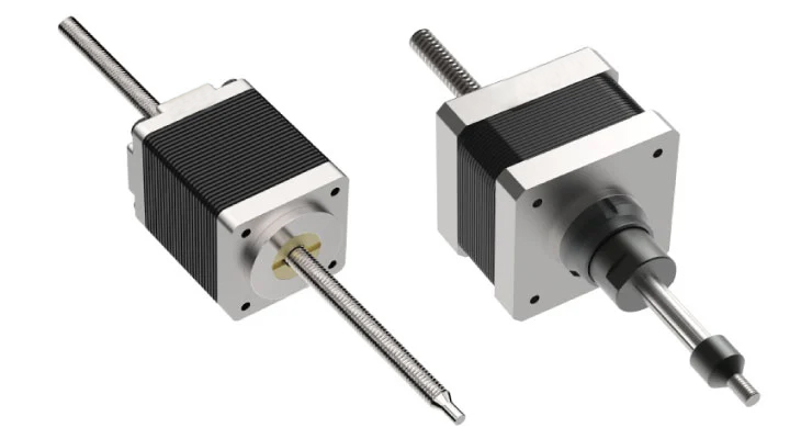
Understanding Captive vs. Non-Captive Linear Stepper Motor Actuators

For a lead screw linear actuator to convert rotary motion into linear motion, there must be an anti-rotation element on the nut design where the lead screw is rotating. The anti-rotation feature applies to an external linear actuator design as well. However, for captive and non-captive linear actuators where the nut is integral to the rotor and confined within the motor, the lead screw is prevented from rotating to translate rotary motion into linear motion.
Captive Style Linear Actuators
In a captive linear actuator design, the lead screw is connected to a spline shaft that passes through a spline bushing to keep it from rotating. The spline bushing prevents the lead screw from rotating but allows enough clearance for the shaft to move axially as the lead screw is driven back and forth with a corresponding clockwise and counterclockwise turn of the motor. The anti-rotation feature is inherent in the design and creates a stand-alone unit that pushes and pulls whatever device it is attached to. Because it is independent, this type of actuator can also provide a push force without being attached to anything. For this reason, it's an excellent choice for packaging applications or push-button applications where the return motion is handled by a spring pre-load or influenced by gravity.
Valves used to control the flow of liquids are excellent applications for this product because the captive actuators can easily open and close them with speed control and accuracy. Captive actuators can also be used to control airflow in HVAC systems with automated dampers in the ductwork. They work particularly well due to their quiet operation, compact size, and function in dusty/dirty environments.
Non-Captive Style Linear Actuators
In a non-captive actuator linear actuator, the lead screw does not have an anti-rotation feature. External mechanical components separate from the motor are introduced into the design to keep the lead screw from rotating. The lead screw moves back and forth axially by restricting its rotation, which then drives the device attached back and forth.
A non-captive actuator is more straightforward and more compact than a captive linear actuator. It is an excellent option when the machine design already includes a built-in guide mechanism or anti-rotation feature and is not needed in the motor as supplied with the captive actuator. The lead screw can be provided longer, supported at each end, and held in tension in specific applications.
Typical applications for non-captive linear actuators include valve controls, inspection equipment, test equipment, semiconductor applications, fluid dispensing systems, blood analyzers, and surveillance video camera focusing mechanisms. Multiple motors can be installed on the same lead screw. The machine design can be set up to run various motors independently on the same axis making non-captive actuators an excellent choice for paper handling, food processing, semiconductor chip manufacturing, and textile applications.
Captive and non-captive linear actuator construction is essentially the same, except for the anti-rotation piece built into the front of the captive motor. Sizes range from NEMA 8 to NEMA 34 in single and double stack motor lengths, with available leads ranging from 0.3 mm to 50 mm advancement per revolution (depending on the motor size). These options provide a variety of package sizes, speed, and resolution options to meet your specific application needs. Both captive and non-captive actuator styles are durable assemblies that offer high-performance, precision applications that operate in demanding environments. Compared to other actuator styles, these linear actuators provide an efficient method to create linear motion at a low cost.
Additional customization for captive and non-captive linear actuators include the addition of optical encoders. Optical encoders can be used for position feedback with a hole in the cover to allow the lead screw to pass through all stroke lengths. Hall sensors tripped by a magnet can be mounted on the end of the lead screw to set the end of the travel limit switch.
Contact our application engineers today for more information or guidance in selecting the correct captive or non-captive linear actuator for your application.


