Pay Attention to This When Selecting Linear Guide System
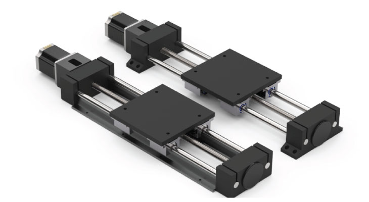
Linear Guide Systems are perhaps the most diverse group of products in the motion control industry. Available in numerous configurations with widely varying performance characteristics, selecting the right linear guide system for your application can be challenging. One of the essential characteristics to consider is guide rail performance -- primarily based on speed, load-carrying capacity and moment load limitations. Load limits for linear guide systems depend on the orientation of the slide and the position of the mass being moved. Therefore, carefully consider whether the system will consist of a single axis, or will require multiple axes, such as in a stage or gantry system.
Space constraints can be another determining factor in the selection process. For example, base size, cross-section and stroke length ratio compared to the overall length of the system will help narrow down the appropriate choices. Other characteristics to consider in system selection are cost, smoothness of operation, noise and preference or familiarity of the guide rail system to the designer.
Types of Linear Guide Systems
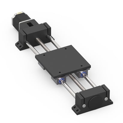

Figure 1: Helix Linear 212 series linear guide system shown with round shaft guide rails
Round Rails
Linear guide systems utilizing round rails feature ball bushings or sliding bushings options. They can be free-spanning or fully supported on an I-beam structure. Round shafting offers low to moderate load-carrying capability as a result of rail deflection. The load limit is highly dependent on the rail length as the rails are designed to be supported on each end. The longer the rail, the greater the potential deflection when radially loading the guides.
When using the round rails, larger diameter rails can provide higher load limits when needed. However, bushings with a larger outer diameter are also required, often leading to space constraints. Round guide rails are ideal for applications with a vertical orientation where the load does not impact the rail because there is little or no side load on the shaft. In addition, recirculating ball bushings provide low friction for smooth operation along the travel length.
A round rail bushing may be less design-friendly based on the round outside diameter and means of finding a way to capture it in the actual assembly. The height and overall position of both ends of the round shaft should be designed to line up, ensuring overall system alignment. Properly designed end mounts help make this alignment easier.
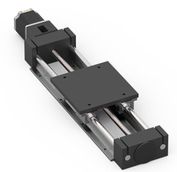
Figure 2: Helix Linear 252 Series linear guide system shown with fully supported round shaft guide rails.
As an alternative, round shafting can be mounted on a structure that fully supports the guide rail and removes deflection concerns. In many cases, a smaller diameter rail can be used as a result. The rails are mounted to I-beam support where the base has mounting feet to secure the linear guide system along the entire length of travel. This configuration supports the movement of heavy loads and is ideal in industrial applications.
Round rail linear guide systems are also available with plastic guide bushings. These low friction sliding bearings, usually combined with PTFE additives, are lower in cost and generally smaller than recirculating ball bushings. Though they can provide higher design flexibility due to reduced size, plastic guide bushings are designed for use in applications with light loads.
Although considered low friction, the friction drag is higher in linear guide systems with round rails and plastic guide bushings. The system motor should be adequately sized to account for the higher torque required to move the carriage. The downfall to this type of friction bearing is that it doesn’t support overhung or moment loads well. As a result, the friction increases significantly, and binding can occur. In addition, the stiffness of the system is greatly reduced due to clearances in the bushing and material deflection. Though they have limitations, plastic slide bushings are ideal for dusty, dirty environments and may eliminate the need for a bellows or cover to protect the rails.
Profile Rails
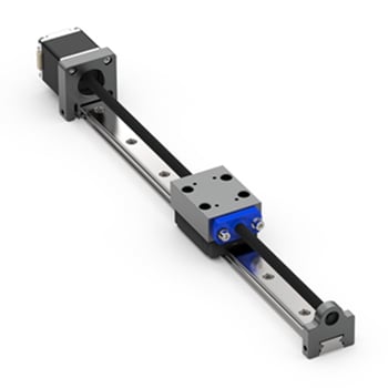
Figure 3: Helix Linear Guide System with single profile rail.
Profile Rails (often referred to as square rails) provide low-friction, smooth guiding systems with high accuracy and stiffness. The square rail design provides support for loads where the center of gravity is directly above the guide rails and also provides the ability to handle moment loads. Square profile rails use recirculating balls in runner blocks called carts, trucks or carriages that the payload attaches to.
Profile Rails can be mounted both vertically or horizontally. When mounting horizontally, consideration should be given to whether the linear guide system will be mounted flat with the load resting on top of the runner blocks, on its side or hung upside down. For moment loads, profile rail assemblies are rated differently in yaw, pitch and roll directions. Therefore, care must be taken not to exceed the load limit based on the mounting position.
If the load is exceeded, utilization of two runner blocks per guide rail can be a solution. However, it may reduce the stroke length or require a longer overall length to achieve the stroke needed. If space constraints are a factor, profile rails can be designed with longer runner blocks to handle higher moment loads. Many profile rail guide systems also have wider rail and wider runner block options available.
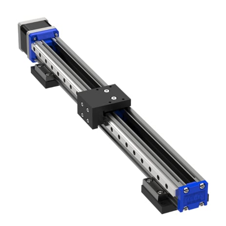
Figure 4: Helix Linear miniature precision actuator with dual profile rail guides.
Profile Rails have more design versatility for mounting due to the flat-mount surface of the runner blocks and tapped holes that secure the base or mating component that is being moved. In addition, profile rails are relatively simple to align when the mating part has a slightly raised milled or ground shoulder to use as a registration edge or datum. The edge of the profile rail can be pushed up against the shoulder during assembly to ensure proper alignment.
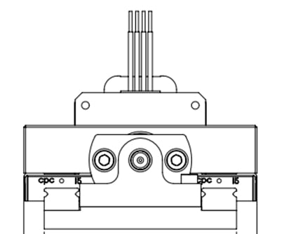
Figure 5: Helix Linear guide system with dual profile rail guides.
Roller Slides
Roller slides provide a very economical means for linear system guidance, generally constructed of lightweight aluminum with four rollers inside the carriage that runs on hardened shafts. Roller Slides are suitable in applications requiring high speeds with large on-axis loads and moment loads. In addition to providing a stable and accurate means for linear motion and a low design profile, they are also a low-noise solution vs. their recirculating ball counterparts.
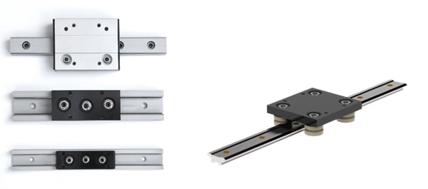
Cross-roller Slides
Cross-roller linear guide systems have cylindrical rollers in v-groove races (instead of recirculating balls). The roller bearings have an alternating 90-degree pattern to support the load. The cost is higher than other guide rails but comes with added benefits. Cross-roller guide rails provide superior stiffness and stability with low noise and smooth operation. They are specifically designed for applications requiring very high loads and moment loads.
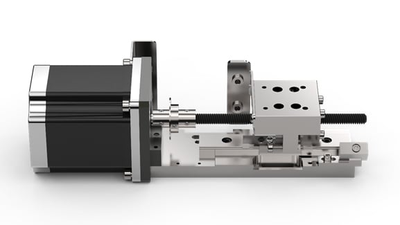

Figure 7: Helix Linear custom linear guide system with cross-roller bearing.
Extrusion Guides
One of the most economical ways to create a linear guide system is through extrusions. Built-in characteristics can function as guides and anti-rotation features with the assembly itself. Generally, these are friction slides that run on a track inherent in the shape, either internally or externally. Design simplicity makes extrusion guides beneficial in applications with limited amounts of space. While the accuracy and stiffness of extrusion guides may not be as high as other available choices, it can be an ideal solution when other guide rails are overkill for the technical requirements.

Figure 8: Helix Linear electric cylinder product (left) and MPA linear guide system with PTFE slide on extrusion.
How to Choose the Best Linear Guide System?
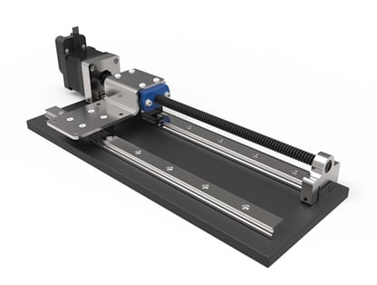
There is certainly overlap in both cost and performance characteristics of the linear guide systems offered. In these cases, the ability to customize the system for OEM designs can help define which option to choose as the foundation for your project. Environmental concerns can also be a deciding factor. Consider requirements such as dust/dirt vs. cleanroom compliant options, high or low-temperature requirements and if industrial strength or food-grade materials are necessary. These conditions will significantly impact the system design and influence decisions such as using lead screws vs. ball screws, and whether incorporated materials need specific chemical resistivity or low outgassing properties.
Choosing a linear guide system supplier should also factor into your system design decision. For example, some manufacturing partners provide high-level assembly capabilities and offer testing services before shipping. As a result, they provide a turnkey solution that works right out of the box, helping you reduce assembly time, eliminate alignment issues, and save valuable time and money.
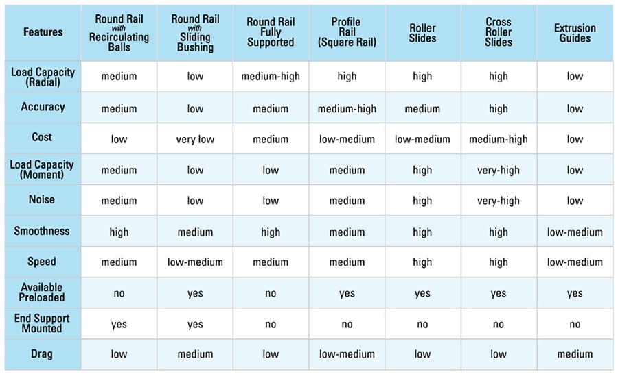
The chart below helps summarize each type of linear guide system and ranks and compares multiple selection attributes. System designers should also consult with the manufacturer’s application engineering team to assist in making optimized selections based on your specific application requirements.
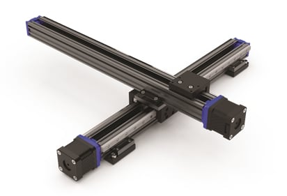
Figure 10: Helix Linear custom multi-axis linear guide System with profile rails and extrusions.
For additional assistance with linear guide system design and selection, get in touch:
